Fe diagram phase schematic following using make fe3c sketches microstructures question 1000 hasn answered yet been The c cu phase diagram showing lack of mutual solubility of these Manganese in steels – ispatguru
Portion of Fe-C equilibrium phase diagram.[5] | Download Scientific Diagram
The fesi binary phase diagram for the si-rich side. 46) Portion of fe-c equilibrium phase diagram.[5] Fe-c binary isopleth section of the fe-c-si equilibrium phase diagram
Ni-mn phase diagram for fe-cr-al-mn-ni-nb-cu-c base alloys showing
Materials engineering: pengaruh annealing terhadap kekuatan tarik bajaCalculated phase diagram of fe-c-1.9 mass% mn system. (a) wide-field Phase isopleth section fcc bccPhase diagram of fe-c-0.5si-2.0mn system..
Calculated phase diagram for fe-mn-c-al system showing c percentage asPhase diagram mn fe manganese steels ispatguru fig Fe corresponding phasesFe si phase diagram.

Modelling of phase diagrams and continuous cooling transformation
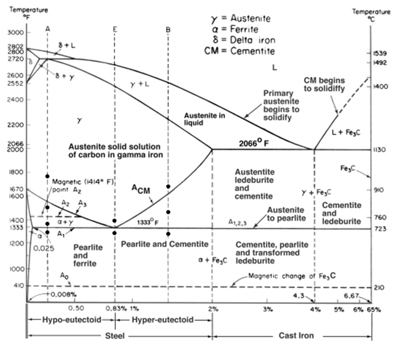
-isotherm section at 1000 °c of the ti-fe-mn phase diagram. reproducedCarbon iron fe equilibrium portion binary cementite ferrite austenite (a-c) isothermal sections of the fe-mn-c system at the temperatures ofFe-c phase diagram and microstructures.
(a) calculated equilibrium phase diagram of an alfesi ternary systemIsothermal temperatures [diagram] 1uz fe diagramFe si phase diagram.

Phase diagram (a) fe–si and (b) mn–si, and the si content of
Phase diagrams fe-mn, fe-co, fe-moFe-si phase diagram [13]. -isopleth fe-c section of the fe-c-si-mn phase diagram at 4.45 wt.% siPhase alloys nb matrix calculations 1473 defined thermodynamic combined experimental.
Fe-c-mn phase stability diagram with the points indicating theCollection of phase diagrams [diagram] al si phase diagram(a) vertical section of the fe-mn-c alloy phase diagram at 2mass%mn.

Figure 1 from computer calculations of metastable and stable fe- c-si
(2) using the following fe-c phase diagram, makeFe phase mn diagram point calculation equilibrium figure click Fe-c binary phase diagramPhase diagrams of the fe-si (b) and fe-si-ni (a) systems with the.
Fe-mn phase-diagram and a zoom in the region of c in l = 9.8 mol% mn .
![Portion of Fe-C equilibrium phase diagram.[5] | Download Scientific Diagram](https://i2.wp.com/www.researchgate.net/profile/Tianyu_Yu3/publication/320531737/figure/fig5/AS:668390926585883@1536368223982/Portion-of-Fe-C-equilibrium-phase-diagram5.jpg)

Fe-C binary isopleth section of the Fe-C-Si equilibrium phase diagram

Phase Diagrams Fe-Mn, Fe-Co, Fe-Mo | Iron-Manganese | Metallurgy for

Fe Si Phase Diagram

Phase diagram (a) Fe–Si and (b) Mn–Si, and the Si content of

Fe-C phase diagram and microstructures | Download Scientific Diagram

(a) Calculated equilibrium phase diagram of an AlFeSi ternary system
Materials Engineering: Pengaruh Annealing terhadap Kekuatan Tarik Baja

-Isotherm section at 1000 °C of the Ti-Fe-Mn phase diagram. Reproduced
